5. Engineering Design
For the functioning of the Kalpasar Project, a design basis was obtained for all the components; A general arrangement of the components was arrived at and the engineering design and sequence was determined. The criteria, standards, guidelines, measurements, assumptions, and constraints that have been followed in the design of the Kalpasar Project are studied. The material specification, durability of the materials and also the loading and the site-specific seismic design considerations are detailed, which is the basis on which the entire project is designed.
Along with the water levels on Reservoir Side and Seaside are arrived based on the different studies and considering these water levels different components of the Kalpasar Project is designed.
5.1 Components of Kalpasar Project
The Gulf of Khambhat Development Project (Kalpasar Project) is a multi-purpose mega project comprising the construction of a dyke for a length of about 60.13 km connecting the Bhavnagar on the west and Dahej on the east. Based on the bathymetry and soil profile along the 60.13 km alignment, the Dyke is built over three regions, namely: the Intertidal Region at Bhavnagar side (19.83 km), the Gulf Region (26.7 km) and the Intertidal Region at Dahej (13.6 km). The maximum depth in the Gulf Region is -27 m below MSL. The seabed level in the Intertidal Region on the Bhavnagar and Dahej are +4.0 m to + 4.5 m MSL, and from +3.0 m to -5.0 m MSL respectively. Since the bathymetry varies along the entire length of the Dyke, different cross-sections are designed with respect to seabed levels.
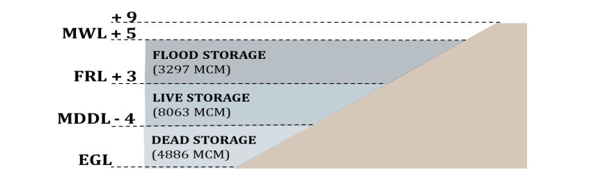
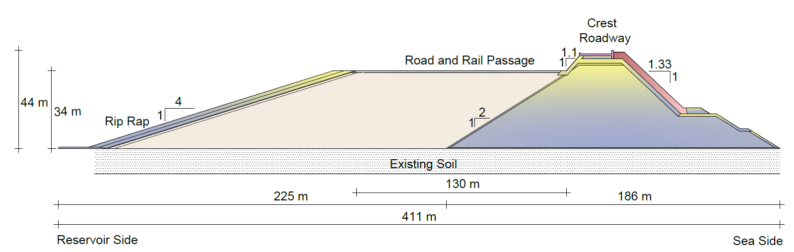
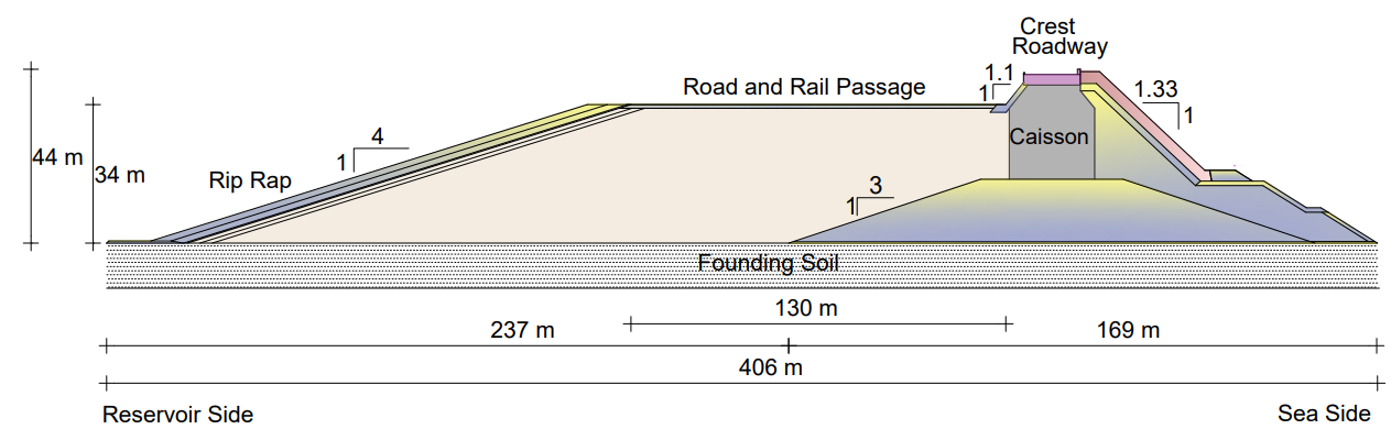
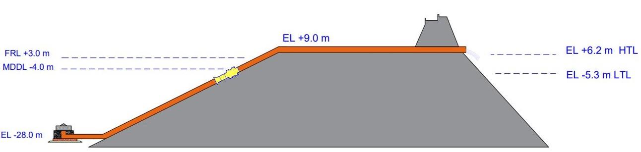
The dyke face on the Seaside is designed as a breakwater using analytical and wave flume studies. The crest level for sections at Gulf is + 19.0 m MSL, and the dyke face on the Reservoir Side is designed as a sand embankment on which the transportation passage is proposed. The crest level on the Reservoir Side is at + 9.0 m MSL in view of the storm surge and seiches in the reservoir. The sand fill embankment on the Reservoir Side is protected by providing the riprap protection. The plastic stress-strain analysis, stability, strength, seepage, and dynamic analyses are carried out of the dyke cross-sections in the Gulf and Intertidal Regions. After performing these analyses and in view of the traffic assessment in the region, the width of the soil embankment is suggested as 140 m.
A flood regulator of 2,010 m wide is proposed in the Dahej Region to regulate the flood flow in the reservoir. The location of the flood regulator is finalized considering the dredging cost and ease of construction. Similarly, a spill channel of width 2,010 m is provided on downstream to match the flow into the sea. The flood regulator has 36 bays, with each bay having a width of 50 m. The upstream apron level is fixed to -7.0 m for a stretch of 43 m. The crest of the ogee weir is – 3.5 m. On downstream of the flood regulator, the stilling basin level is - 12 m for a stretch of 100 m with the energy dissipation mechanism. Beyond the aprons on upstream and downstream protection works (like concrete blocks and sheet piles) are provided to protect the flood regulator against piping and scouring actions.
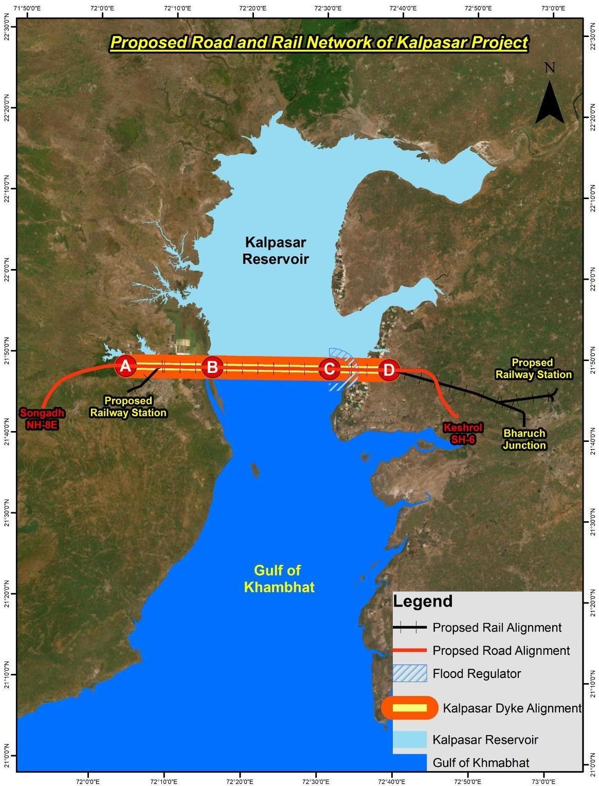
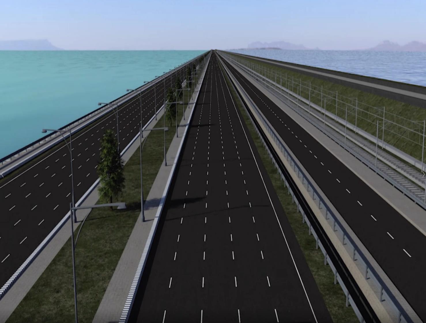
The transportation passage is placed on the sand embankment on the Reservoir Side consists of 16-lane roadways and 4-lane railway tracks. The road alignment on the Bhavnagar side connects the NH 751 and further extended to SH 36 at Ghangalia and NH 8E at Sonegadh. The road alignment on Dahej side connects the Paniyadra and Aladar on SH 6 and extended to NH 64 at Sadathala and SH 6 at Keshrol. The total length of the road alignment is 100.5 km. The rail alignment runs parallel to the road alignment. The rail alignment on the Dahej side connects the existing railway line at Bharuch and on Bhavnagar side, the rail alignment connects the Nari Railway Station. The total length of rail alignment is 97.43 km.
5.2 Dyke Design
The dyke is designed based on the geotechnical and hydraulic studies. On the seaside, the breakwater design and its cross sections are tested for hydraulic stability through physical model studies. No overtopping and splashing of waves were found during the testing for different design water levels, and no damage was seen to any component of the breakwater.
The dyke is analyzed and checked for stability, strength, settlement and seepage in both the Gulf and the Intertidal regions. The analysis has been carried for both static and dynamic cases. The soil test is carried on both the intertidal and Gulf regions and the strength analysis are carried out at different sections. The Gulf region is filled with sandy soil and hence vibro-compaction is recommended over a certain thickness of soil while the intertidal region has soft clay in the top layer, and hence stone columns are recommended as ground improvement. The bearing capacity is found to be critical in intertidal region under dynamic loading condition. The settlement analysis carried out on both construction and creep phase was found to be within the permissible limit (500 mm). The settlement values in dynamic analyses considering acceleration time histories (with PGAs of both 0.225 g and 0.360 g) are also found to be within the permissible limits.
The seepage through the dyke and the foundation soil has been considered for stability using steady state seepage analysis and the volume of seepage and salt flux into the reservoir has been estimated using dispersion study. The dyke was found to be stable for the anticipated seepage and the salt flux into the reservoir was found to be within the permissible limit. The slope stability of the dyke has been analyzed and found to be stable in both static and dynamic conditions. The cross-section of the dyke has been modified, accordingly, to meet all the design criteria and based on the closure strategy adopted for finalizing the cross-section.
5.3 Flood Regulator Design
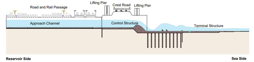
The components of Flood Regulator starting from the upstream end, typically consist of an approach channel, control structure, control gates, an exit chute, an energy dissipater, and a discharge channel. The design of these components is carried out to frequently pass flood from upstream to downstream. In addition to these components, a Fish Pass is designed to facilitate the movement of fishes from upstream to downstream and vice versa. The configuration of the Flood Regulator is chosen to take-up four conditions of flow namely, Subcritical, Critical, Supercritical and Transitional flow. The flow in the approach channel will be a subcritical flow (low velocity) starts accelerating, when it approaches the control section (crest); when the water passes over the crest the flow will become critical and later to supercritical state (high velocity) as it moves below the crest. Further, the flow at or near the terminus of the chute will become a transitional flow, which will transit back to subcritical state when it reaches the sea. Approach channel is designed to convey water from the reservoir to the control structure. The control structure in the present case is a low ogee weir, which will provide a more positive relation between reservoir elevation and discharge and thus, increasing in the efficiency of the Flood Regulator. The channel is designed to direct flows of water from the Flood Regulator to the estuary on the downstream side. The design of spill channel is tied with the design of terminal structure. The spill channel is the confluence point between the terminal structure and the estuary. Terminal structure is designed with energy dissipators to dissipate this high energy and make the flow sub-critical.
Design of the above-mentioned components are carried out considering the hydraulic, geotechnical, and structural aspects of flood regulator. The hydraulic design of Flood Regulator is mainly based on the hydraulic theories involved in uniform flow, gradually and rapidly varied flow, steady and unsteady flow, energy, and momentum principles. The geotechnical design is performed considering various geotechnical criteria which includes bearing capacity, settlement, and uplift in the Flood Regulator components. The structural design of Flood Regulator components is carried out considering the possible loads and load combinations prevailing under various hydraulic flow conditions in the Flood Regulator. The fish pass is designed considering its effectiveness. Facilities are provided for linking the exit of the fishway with the natural bottom or bank substrate to ensure smooth movement of migrant benthic organisms.
5.4 Hydro-mechanical Gate
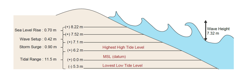
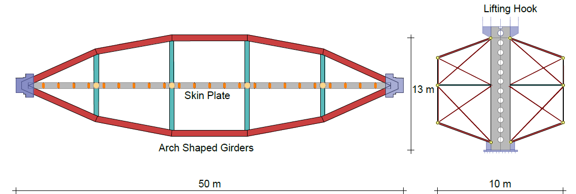
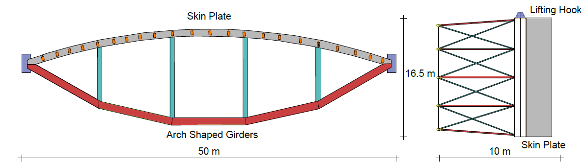
Hydromechanical structures include Service Gates, Maintenance Gates and their operating mechanisms, which aid in discharging water from upstream Side to downstream side during flood scenario while preventing the sea water from entering the reservoir. Service gates are resting over ogee weir at bottom level of – 3.5 m MSL and Maintenance gates are resting over reservoir side apron level of – 7 m MSL. With added free board to Maximum Design Water Level + 8.22 m MSL the gate top level is fixed as +9.50 m MSL for both Service and Maintenance gates. A 50 m Span is adopted to ensure Water tightness, cheaper fabrication and reduced number of gates. Along with the larger span we need to maintain a water level difference from + 5 m [MWL] in reservoir side to – 6.5 m [LLTL] on Sea side of approximately 11.5 m, the horizontal deflection would be high. These deflections be large and visible to naked eye, in case of completely flat gate. To minimize this deflection, lens-shaped gates and girders are preferred. Since, Maintenance Gates of 16.5 m height is resting over a flat Reservoir Side Apron, a Convex Lens shaped gates are preferred. The Service Gate is to be mounted on an Ogee-shaped Weir which has no flat surface in the horizontal plane. So, a flat gate with arched shaped girders is chosen for the Service Gate of 13 m height.
For water to flow though the flood regulator, the gates have to be lifted for opening the regulator, and the water will be released in a controlled manner for closing. Electromechanical system, featuring double winches and a counterweight is adopted as lifting mechanism and will be constructed on 6.0 m wide concrete piers situated longitudinally along the axis of Flood Regulator. To discharge the incoming peak flow of 85,000 m³/s along the Flood regulator width of 2,010 m, total of 36 bays with 36 sets of Service and Maintenance gates are proposed.
5.5 Transportation Design
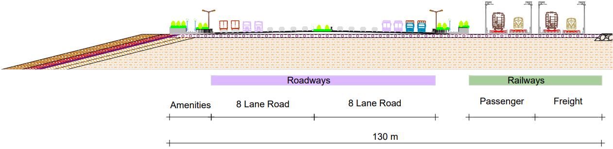
A multi-mode Road and Railway transportation system is proposed to connect the east and the west banks of the Gulf of Khambhat. The sand embankment of width 140 m will be used for multi-mode road and rail passage, which reduces distance from 240 km to 60 km between the east and the west bank of the Gulf. The width of the road and rail passage proposed is 130 m to accommodate the road and the rail alignment. The road and rail passage are placed on the sand embankment on the reservoir side, consisting of 16-lane roadways (8 lanes in each direction) and 4-lane railway tracks (2 tracks in each direction) with dedicated passenger and freight rail lines.
The topographic survey data is considered for dyke portion and till the nearest access roads NH 751 on Bhavnagar side and SH 6 (Dahej - Aladar section) covering the dyke alignment for about 60 km. Total length of road alignment is 100.5 km. The road alignment on the Bhavnagar side connects the NH 751 and further extended to SH 36 at Ghangalia and NH 8E at Sonegadh for effective dispersal of the traffic. The road alignment on Dahej side connects the Paniyadra and Aladar on SH 6 and extended to NH 64 at Sadathala and SH 6 at Keshrol. The road alignment is designed as a National Highway with design speed of 100 kmph. Median opening is provided at 5 km interval for the purpose of emergency U-turn. Interchanges are provided at 8 locations for smooth dispersal of the traffic. The rail alignment runs parallel to the road alignment.
Total length of the rail alignment is 97.43 km and the proposed railway alignment is integrated with existing railway line on Bhavnagar side and Bharuch side. The rail alignment on the Dahej side connects the existing railway line at Bharuch and on Bhavnagar side, the rail alignment connects the Nari Railway Station. New Railway terminals are proposed near Ramdev Nagar in the Bhavnagar side and outskirts of Bharuch on the Dahej side. Rail alignment is designed as semi-high-speed rail for passenger line and as a Dedicated Freight Corridor (DFC) for freight line. Design loadings and load combinations are considered as per prevailing Indian Standards (IS) and Indian Road Congress (IRC) standards.
5.6 Irrigation Design
The command area of Kalpasar Project has been selected in such a manner to avoid overlap of the command areas of existing irrigation schemes (i.e., Saurashtra Narmada Avtaran Irrigation (SAUNI) scheme and other irrigation schemes). There are nine districts in the Kalpasar Command Area and the Gross Command Area is about 18,34,769 ha, while the Cultivable Command Area, after deduction of area irrigated by existing government canals, is worked out as 11,98,169 ha and the total proposed command area for Kalpasar reservoir is 9,99,611 ha. Cropping pattern has been estimated for the project and relevant canal sizing is also used for evaluation of the project from the economic stand point. To accommodate the undulating topography, the main canal comprises of an Open Canal system with Pumping Stations to lift the water and supply it through pipelines. In this connection the following designs have been carried out: Design of Canals, crossing structures on main canal, cross regulators, head regulators, falls, escape, etc.; Design of Underground Pipeline; and Design of Pumping Stations.
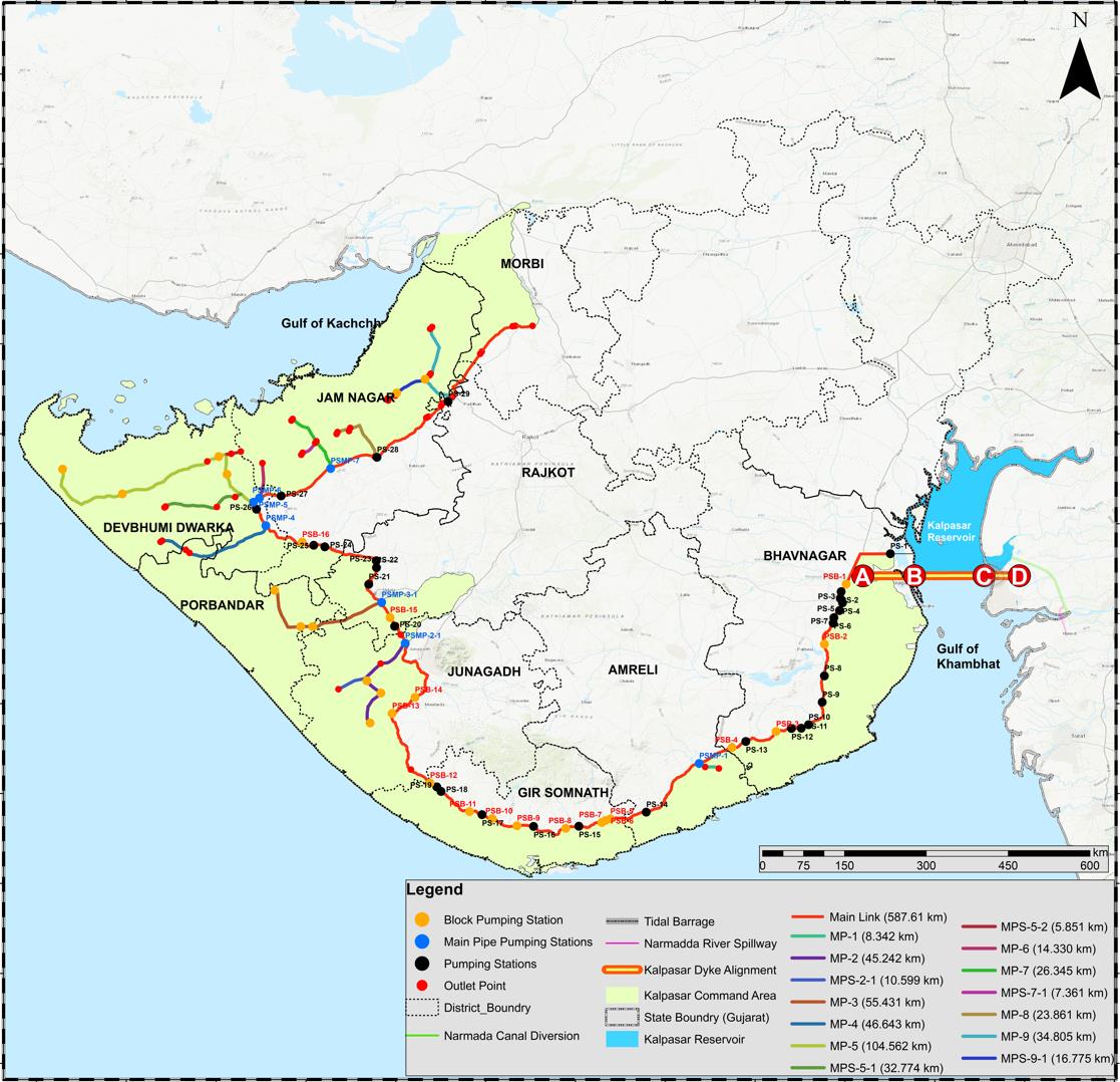
The entire area to be irrigated lies on the west side of the reservoir since the other areas are already covered under the existing Mahi system and the Sardar Sarovar Project. The off-take point therefore is selected as west as possible within the fresh water lake for lifting of water even when the reservoir is at MDDL i.e., MSL. An approach channel will have to be dredged for supply of water into the intake structure. The pumping station is located at off take point which will lift water according to the irrigation requirement and deliver into the canal system.
For drinking water, the water drawn from Kalpasar Reservoir shall be distributed through existing bulk pipeline and pumping stations of Water Supply Department (GoG) and hence the canals will not be used as a carrier for domestic and municipal use water.
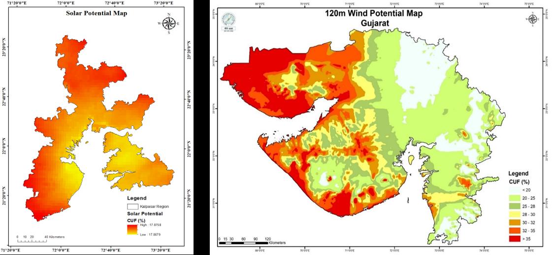
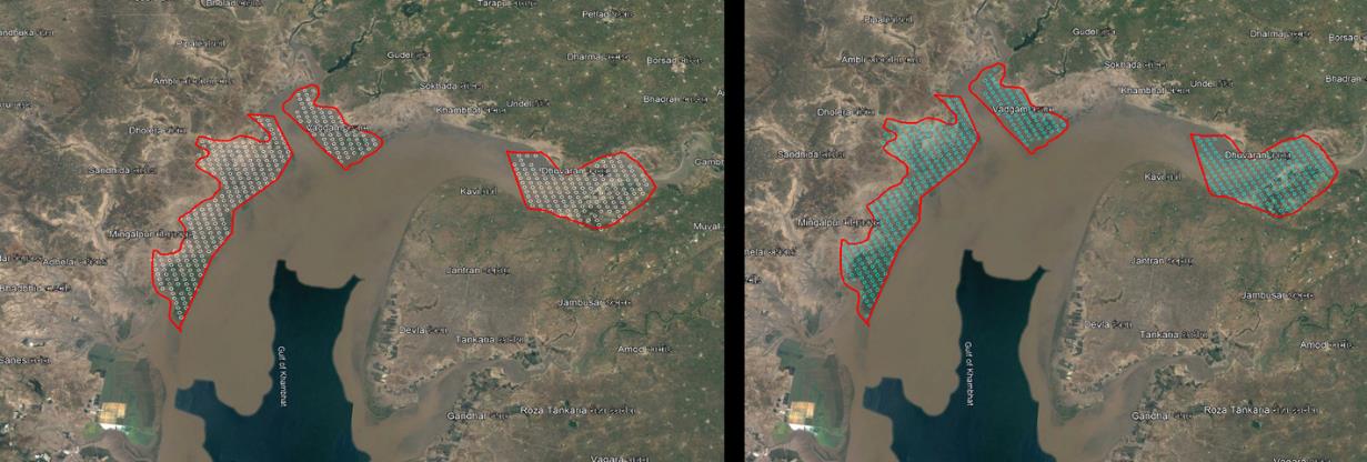
5.7 Renewable Energy Design
The power required for pumping about 4,800 Mm³ of water from the Kalpasar reservoir to Saurashtra region, which is at higher elevation, requires about 3196 MW Power. To meet this power requirement, about 2500 MW capacity wind and solar farms are proposed at three locations. The potential for setting up of hybrid power generation was studied for both wind and solar energy from the pre-existing data. The location was found to have a high potential for power generation. The site-specific conditions have been analyzed and the location of wind mast for the region has been studied for site specific analysis. Based on these studies, it was proposed to implement a hybrid wind-solar power system. The solar farm layout is designed subsequent to the design of the wind farm layout. In order to avoid the shadow impact, a circular mask has been applied to each wind turbine to the extent of fall-off distance, and the solar panels are proposed in the remaining area. After the exclusion of the fall-off distance area, ample amount of land is available for the development of the proposed 1,000 MW solar farm. Two models of wind Farm (3.3 and 3.47 MW) were developed with a total capacity of 1500 MW with total number of turbines as 455 and 435, respectively. Based on the analysis of shadow effect, a total of 4,000 hectares of land is required for generation of 1,000 MW power from solar. A power evacuation scheme, sensitivity analysis and cost-benefit analysis have also been carried out for the Kalpasar project. Based on the study, the levelized tariff for 25 years is estimated to be Rs. 4.07/kWh for wind energy and Rs. 3.64/kWh for solar energy.
5.8 Instrumentation and Monitoring Design
Instrumentation of the dyke and its auxiliary facilities can improve the ability to monitor the performance of the dyke by providing complete and timely information. Instruments are deployed to monitor the performance of foundation and interior of structures and finally quantitatively evaluating the ongoing performance of dyke. The data collected using the instruments are used to capture steady streams of repeatable data. The data from the instruments are displayed live for better supervision of the dyke's performance under both normal and extreme loading conditions. In addition to monitoring the performance of the dyke, the instrumentation data is valuable for research studies. Effective dyke safety monitoring is essential to manage the risks associated with the operation and maintenance of a dyke. The use of instrumentation can improve the ability to monitor the ongoing performance of the dyke by providing more comprehensive and timelier information.
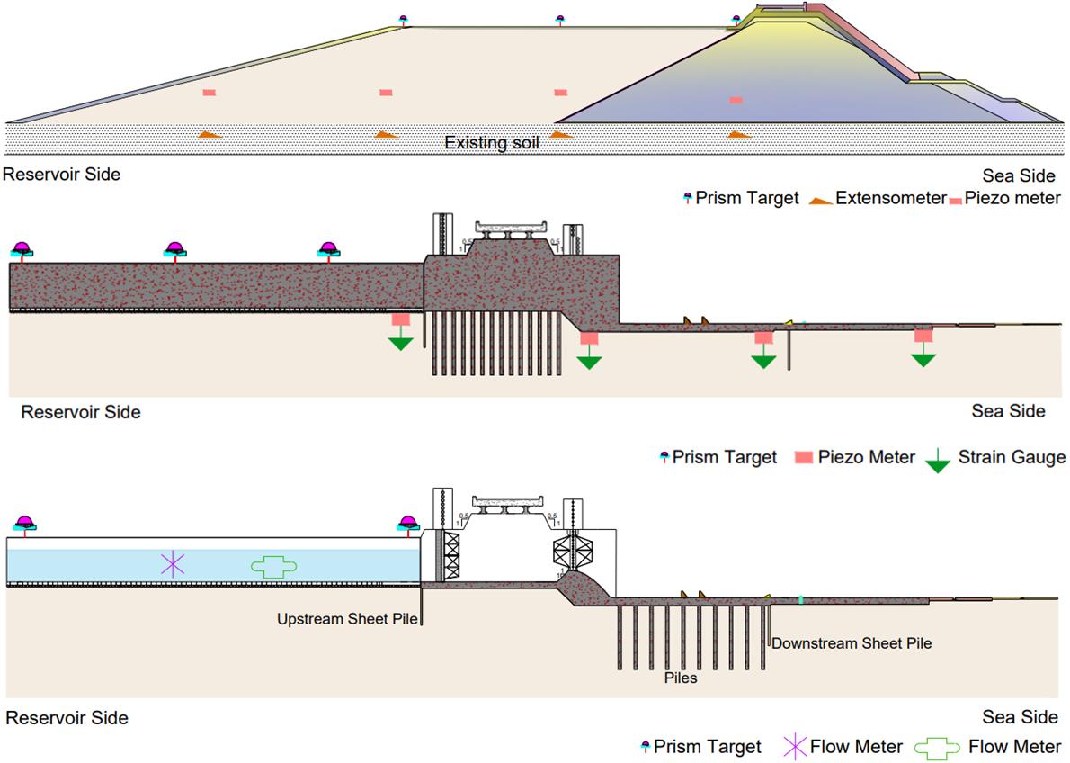
Monitoring needs vary over the distinct phases that occur during the life of a dyke. These phases typically include design, construction, first reservoir filling, long-term (normal operations), and dealing with an unexpected performance. Instrumented monitoring can be an effective tool for obtaining the information needed during these separate phases. In addition to monitoring the performance of the dyke, instrumentation data can also be valuable for litigation purposes or for research studies.
5.9 Construction Sequence
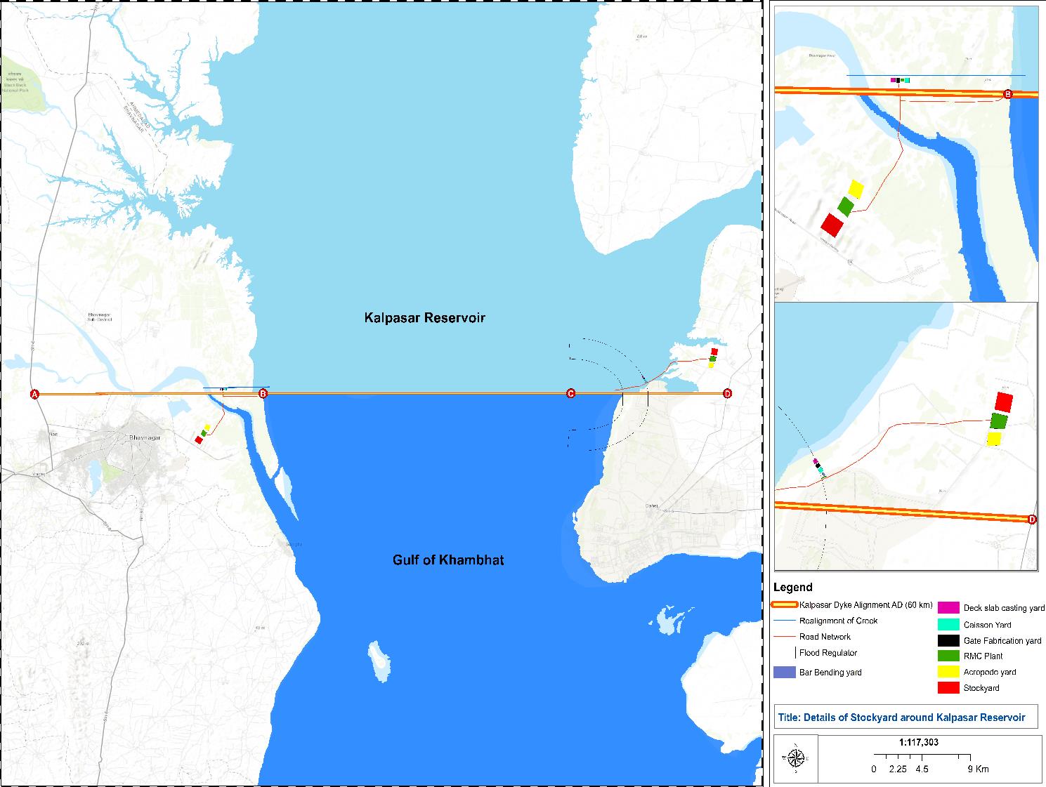
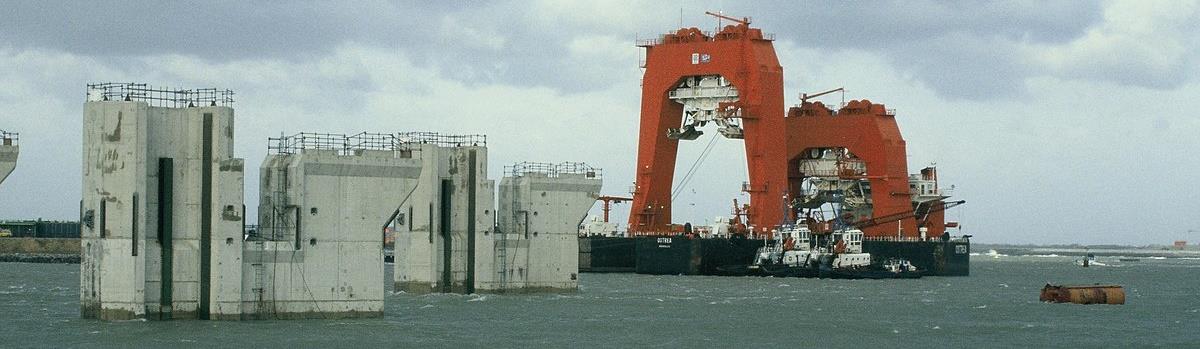
Construction of the Kalpasar Project involves various components that need to be constructed simultaneously. The construction involves proper estimation and management of materials, equipment and logistics, and determination of correct sequence of construction in the planned timeline. The implementation is designed of the Kalpasar project, including sourcing materials for construction, transportation of materials, logistics and equipment involved in the implementation process. The construction and sequencing are presented for timely completion of project. The total materials required for the Kalpasar project is estimated and source of the materials are identified. Then the materials are transported by the different modes of transport, namely roadway, combined road and railway, and Water borne network. Based on the cost and distance of the route from the source to project site, mode of transport is selected. To carry the different construction materials at the project sites, various yards are constructed near to the dyke alignment on east and west side. Materials are required to carry the 15 days of work is planned to be stored in the stack yards. Based on the requirements the area for the stack yard and remaining yards are calculated. To construct the overall project different type of equipments are identified. Based on the usage in construction, customized equipments are also been identified. One of the main customized equipment is Special Lifting Vessel (SPV). SPV is used to transport the caisson from the casting yard to the gulf during the closure works.
The construction sequence for different components is arrived based on their design. The construction of dyke in intertidal region and gulf region are carried out parallelly. In addition to this, the construction of flood regulator component is also carried out simultaneously along the dyke construction. In intertidal region the construction of dyke starts with the ground improvement techniques and followed by the construction of dyke. In gulf region, the construction starts with the closure works and then followed by the post closure works.
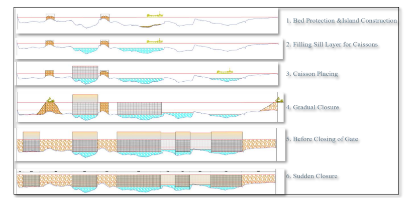
Closure works in Dyke is a critical sequence arrived based on the dyke closure design. In dyke closure, first the temporary jetty is constructed for transportation of materials and equipment. Once the jetty construction is completed, the construction of islands, bed protection and laying of vertical sill and gradual horizontal closure by means of end-on construction is also carried out. Once all the caissons are placed and the horizontal closure is also completed, then sudden closure of gates is carried out. This concludes the closure component. The caissons are to be filled with sand on the reservoir side and on the Seaside, the slope is made to 1:1.33 slope, by means of erecting the toe. The core, underlayer and armour are placed, in that order. The vibro-compaction of the embankment is also simultaneously carried out and finally levelled to +9 m MSL. A transportation corridor and the other developments are then carried out over the Dyke section. Simultaneously, the construction of flood regulator component is also carried. A total of 7.5 years is required to complete the overall Kalpasar project. Special Purpose vessels that have to be custom-built have also been arrived at for closure of the dyke.
5.10 Dyke Closure Design
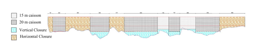
The critical part of the dyke construction is the closure of the dyke in the Gulf region, where the velocity of the flow increases during the closure process. Hence, the materials that are used should withstand these increased velocities due to hydrodynamic effects; this is an important task for the completion of the project. Site-specific closure methods are available for closure of the entire dyke alignment. In the Gulf, a full horizontal closure (without any open structure) leads to a maximum flow velocity up to 10 m/s and is therefore not feasible. A full vertical closure (without any open structure) leads to a maximum flow velocity of 6 m/s and might be feasible. Hence the operation of vessels at this velocity becomes impractical. Therefore, construction of the entire dyke as vertical closure might not be feasible. The maximum flow velocity is strongly dependent on the length of the concrete structure. When the total length of the gap increases, the maximum flow velocity through the section reduces. The maximum flow velocity decreases linearly with an increase in caisson height because a smaller area underneath needs to be filled up and so the cross-section of flow increases.
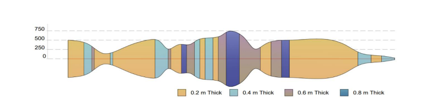
It is understood that sudden closure is necessary in this location. The gates of the caisson are to be closed during the slack tide. Nevertheless, the changing conditions during execution of closure works are difficult to predict. Closure works can happen more than one tidal cycle and hence the gap is exposed to maximum velocities during closure. Sometimes construction can happen more than a week. During such situation, closure can be halted during spring tides to avoid high velocities. Stone size of 40 – 200 kg have been proposed to be used at the closure sections. It has been analysed, that storm surge and wave heights also influence the stone stability. Hence the vertical sill is designed to be maintained below the depth of influence of the wave and the horizontal components are to be simultaneously protected with armour units while the exposed face of the horizontal component, if damaged can be rectified, in case of major events. The bed protection is designed to prevent the scour from influencing the stability of the dyke. It is proposed to provide the bed protection to a maximum width of 1.4 km and a maximum thickness of 0.8 m along the entire dyke section. The scour also gets influenced during the halt period. Additional protection has to be provided where the work is halted.
5.11 Saline Water Decanting Design
For removing the saline water from the reservoir, three options, are examined namely; sluice gates, siphon and pumps. After careful examination, pumps are found to be effective as the decantation is performed only during the initial stage of the project. The submersible pumps are recommended, which can be installed along the pipe and can work efficiently even with a variable head.
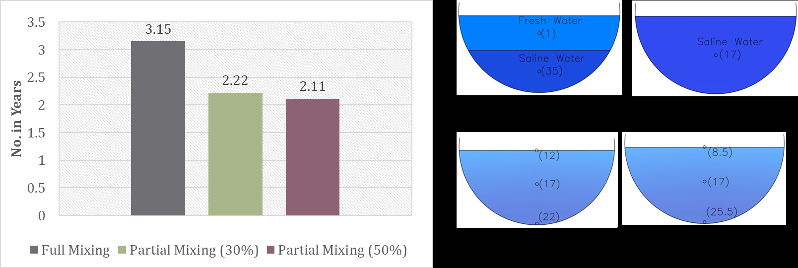
A total of 35 pumps are needed to ensure that the water level in the reservoir does not go below MDDL during the decantation process. For estimation of the time required for decanting the saline water, a basin storage model is used to simulate 4 years of inflow from the reservoir considering 50% water availability, losses due to evaporation and outflow due to pumping. Four scenarios for salinity stratification are studied, namely: (a) No Mixing, (b) Full Mixing, (c) Stratification with 30% denser fluid at the bottom, and (d) Stratification with 50% denser fluid at the bottom.
The results indicate that 300-day as lower limit (in the No Mixing case) and 3.15 years as upper limit (in the Full Mixing case). The more realistic scenarios will be stratified with 30% and 50%, which indicate a timeline of around 2.2 years to reach a salinity of 2 ppt. Also, the estimated cost for decantation is about Rs. 900 Crores, including both capital and operation costs.